Modeling Complex 3D Shapes with the Solid Tools使用Solid Tools对复杂的3D形状进行建模
With SketchUp’s Solid tools, you can create new shapes by combining or cutting one shape with another, making it easy to model an outer shell or joinery.使用SketchUp的Solid工具,您可以通过将一个形状与另一个形状组合或切割来创建新的形状,从而轻松地对外壳或细木工制品进行建模。
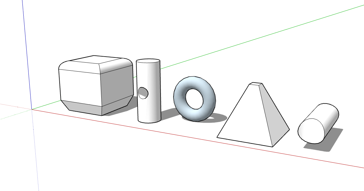
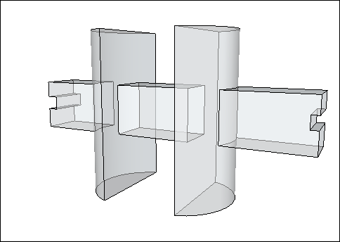
In SketchUp, a solid is any 3D model (component or group) that has a finite closed volume. 在SketchUp中,实体是具有有限封闭体积的任何三维模型(组件或组)。A SketchUp solid cannot have any leaks (missing faces or faces that do not meet at an edge). The following image contains several solids.SketchUp实体不能有任何泄漏(缺失的面或边缘不相交的面)。下图包含几个实体。
Check out the following table for a quick introduction to the Solid Tools, including what the tool does and whether it’s available in SketchUp Free.查看下表,快速了解Solid Tools,包括该工具的功能以及它是否在SketchUp Free中可用。
To find the Solid Tools, look in the following parts of the SketchUp interface:要查找Solid Tools,请查看SketchUp界面的以下部分:
SketchUp Pro
Solids toolbar实体工具栏Tools menu (Select Tools > Outer Shell or Select Tools > Solid Tools and select the other tools from a submenu)工具菜单(选择工具>外壳或选择工具>实体工具,然后从子菜单中选择其他工具)Tool palette (macOS)工具选项板(macOS)
SketchUp for Web
Solids toolbar in the left-hand tray左侧托盘中的实体工具栏Solid Inspector utility in the right-hand panel右侧面板中的Solid Inspector实用程序
In the following video, you see examples of the Solid tools in action. In the following sections of this article, you will find steps and details about using each tool. 在以下视频中,您将看到Solid工具的实际应用示例。在本文的以下部分中,您将找到使用每种工具的步骤和详细信息。(Note, however, that you can't place SketchUp models in Google Earth anymore.)(但是请注意,您不能再将SketchUp模型放置在Google Earth中。)
Table of Contents目录
Creating an outer shell创建外壳Uniting solids into a single form将固体组合成单一形式Subtracting one solid from another (or use Intersect Faces with Model)从一个实体中减去另一个实体(或使用模型的相交面)Trimming one solid with another用一个实体修剪另一个实体Leaving only the intersecting geometry只留下相交的几何图形Splitting solids拆分固体- SketchUp Web:
Fixing Models with Solid Inspector使用Solid Inspector修复模型
Creating an outer shell创建外壳
The Outer Shell tool (“外壳”工具(![]() ) removes geometry inside overlapping groups or components, leaving only the outer faces.
) removes geometry inside overlapping groups or components, leaving only the outer faces.![]() )删除重叠组或组件内的几何图形,只留下外表面。
)删除重叠组或组件内的几何图形,只留下外表面。
For example, say you have two models: One is a detailed interior and exterior building model. The other model illustrates the building in a street view that shows surrounding buildings, streets, and landscaping. You can import the detailed building model into your street view. 例如,假设您有两个模型:一个是详细的内部和外部建筑模型。另一个模型在街景中显示了建筑,显示了周围的建筑、街道和景观。您可以将详细的建筑模型导入到街道视图中。However, all that geometry might slow down your street view model and isn’t necessary. 但是,所有这些几何图形可能会减慢街景模型的速度,并且不是必需的。In your street view, creating an outer shell of the building eliminates the interior geometry you don’t need so that your street view model is lighter and renders faster as you work on it.在街景中,创建建筑的外壳会消除不需要的内部几何图形,这样您的街景模型在处理时会更轻,渲染速度更快。
To create an outer shell from overlapping groups or components, follow these steps:要从重叠的组或组件创建外壳,请执行以下步骤:
SketchUp Pro
With the Select tool (使用“选择”工具( ), select all the intersecting groups or components you want to include in your outer shell.),选择要包含在外壳中的所有相交组或零部件。
Context-click your selection and choose Outer Shell from the menu that appears, as shown in the figure.右键单击您的选择,然后从出现的菜单中选择“外壳”,如图所示。The outer faces remain.外表面仍然存在。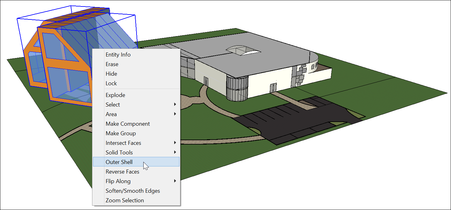
Or, you can create an outer shell as follows:或者,您可以按如下方式创建外壳:
Select the Outer Shell tool (选择“外壳”工具( ).)。Tip:
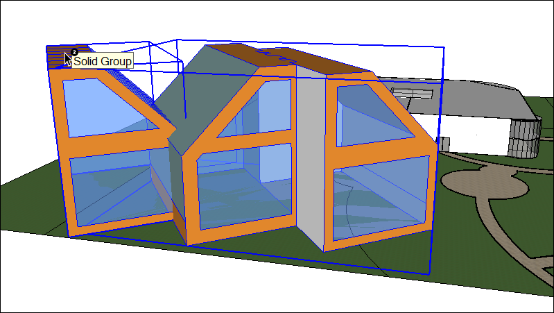
Until you hover over a solid group or component, you see an arrow cursor with a circle and a slash. When your cursor hovers over a solid group or component, the red circle and slash change to a black 1 inside a circle, and you see a Solid Group or Solid Component ScreenTip.在将鼠标悬停在实体组或组件上之前,您会看到一个带有圆圈和斜线的箭头游标。当游标悬停在实体组或组件上时,红色圆圈和斜线会变为圆圈内的黑色1,您会看到实体组或实体组件屏幕提示。Click to select the first group or component in your outer shell.单击以选择外壳中的第一个组或组件。Click the second group or component. SketchUp combines your selections into an outer shell so that only the outer faces remain.单击第二个组或组件。SketchUp将您的选择组合到一个外壳中,这样就只剩下外表面了。(Optional) Continue clicking additional groups or components to add them to your outer shell, as shown in the figure.(可选)继续单击其他组或组件,将其添加到外壳中,如图所示。
SketchUp for WebSketchUp for WebSketchUp for Web
Select the Outer Shell tool (从左侧工具栏中选择“外壳”工具() from the left hand tool tray.)。Tip:Until you hover over a solid group or component, you see an arrow cursor with a circle and a slash. When your cursor hovers over a solid group or component, the red circle and slash change to a black 1 inside a circle, and you see a Solid Group or Solid Component ScreenTip.在将鼠标悬停在实体组或组件上之前,您会看到一个带有圆圈和斜线的箭头游标。当游标悬停在实体组或组件上时,红色圆圈和斜线会变为圆圈内的黑色1,您会看到实体组或实体组件屏幕提示。Click to select the first group or component in your outer shell.单击以选择外壳中的第一个组或组件。Click the second group or component. SketchUp combines your selections into an outer shell so that only the outer faces remain.单击第二个组或组件。SketchUp将您的选择组合到一个外壳中,这样就只剩下外表面了。(Optional) Continue clicking additional groups or components to add them to your outer shell, as shown in the figure.(可选)继续单击其他组或组件,将其添加到外壳中,如图所示。
Uniting solids into a single form将固体组合成单一形式
A union merges two or more solid entities into a single solid.联合将两个或多个实体合并为一个实体。
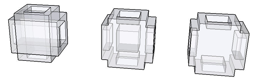
The result of a union is similar to the result of an outer shell. However, the result of a union can contain internal geometry whereas an outer shell contains only external faces. (See the preceding figure for an example.)结合的结果类似于外壳的结果。但是,联合的结果可以包含内部几何图形,而外壳只包含外表面。(示例见上图。)
Here’s how to use the Union tool to combine solid entities:以下是如何使用Union工具组合实体:
Select the Union tool (
 ).Tip:
Until you hover over a solid group or component, you see an arrow cursor with a circle and a slash. When your cursor hovers over a solid group or component, the red circle and slash change to a black 1 inside a circle, and you see a Solid Group or Solid Component ScreenTip.在将鼠标悬停在实体组或组件上之前,您会看到一个带有圆圈和斜线的箭头游标。当游标悬停在实体组或组件上时,红色圆圈和斜线会变为圆圈内的黑色1,您会看到实体组或实体组件屏幕提示。Click to select the first group or component for the union.单击以选择联合的第一个组或组件。Click the second group or component. The resulting union of the geometry remains.单击第二个组或组件。几何图形的合并结果仍然存在。(Optional) Continue clicking additional groups or components to add them to the union, as shown in the figure, which uses X-Ray view so that you can see the geometry within each solid.(可选)继续单击其他组或组件以将其添加到联合中,如图所示,该联合使用X射线视图,以便您可以看到每个实体内的几何图形。
Subtracting one solid from another (or use Intersect Faces with Model)从一个实体中减去另一个实体(或使用模型的相交面)
With the Subtract tool, you can use one solid entity to cut another solid entity. Your original solid entity is then subtracted from the model. For the subtraction to work, the two solids need to overlap.使用减法工具,可以使用一个实体切割另一个实体。然后从模型中减去原始实体。为了使减法有效,两个实体需要重叠。
To perform a subtraction, follow these steps:要执行减法,请执行以下步骤:
Select the Subtract tool (
 ).Tip:
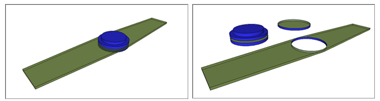
Until you hover over a solid group or component, you see an arrow cursor with a circle and a slash. When your cursor hovers over a solid group or component, the red circle and slash change to a black 1 inside a circle, and you see a Solid Group or Solid Component ScreenTip.在将鼠标悬停在实体组或组件上之前,您会看到一个带有圆圈和斜线的箭头游标。当游标悬停在实体组或组件上时,红色圆圈和斜线会变为圆圈内的黑色1,您会看到实体组或实体组件屏幕提示。Click to select the cutting group or component. In the example shown here, select the peg first to make a hole in the board. After you make a selection, the 1 next to the cursor becomes a 2.单击以选择切割组或组件。在此处显示的示例中,首先选择钉子在板上打孔。选择后,游标旁边的1将变为2。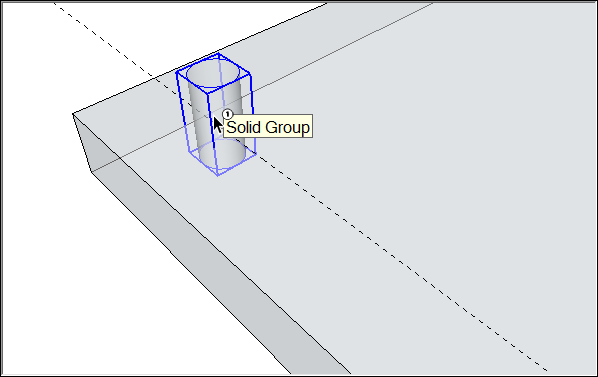
Click the group or component that you want to cut. The cutting group disappears, but makes a hole in the second selection. In this example, you see a peg-sized hole in the board.单击要剪切的组或组件。切割组消失,但在第二个选择中留下一个洞。在这个例子中,您会看到板上有一个钉子大小的孔。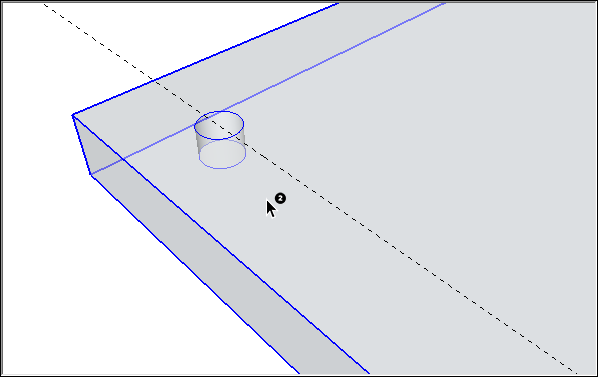
If you’re using SketchUp Free, you can create the effect of a subtraction by using the Intersect with Model command. When you use Intersect with Model, the two shapes don’t need to be solid entities. 如果使用SketchUp Free,则可以使用“与模型相交”命令创建减法效果。当您使用“与模型相交”时,这两个形状不需要是实体。(In fact, Intersect with Model applies a different effect if your shapes are solids, as explained a little later in this section.) However, when you create a subtraction with the Intersect with Model command, the process requires a few more steps than the process with SketchUp Pro’s Subtract tool.(事实上,如果您的形状是实体,则“与模型相交”会应用不同的效果,如本节稍后所述。)但是,当您使用“与模型交集”命令创建减法时,该过程比使用SketchUp Pro的“减法”工具的过程需要多几个步骤。
Here’s how to create a subtraction with the Intersect with Model command:以下是如何使用“与模型相交”命令创建减法:
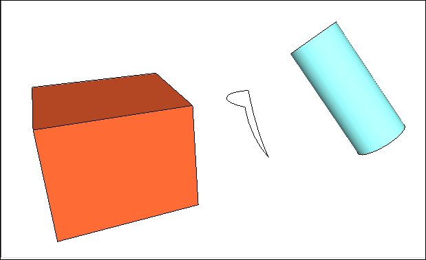
Create two distinct volumes, such as a box and a cylinder. (See Drawing Basic Shapes and Pushing and Pulling Shapes into 3D for help.)创建两个不同的体积,例如长方体和圆柱体。(有关帮助,请参阅绘制基本形状和将形状推拉到3D中。)With the Select tool (使用“选择”工具(), triple-click the first volume, which will be your cutting object. ),三次单击第一个体积,这将是您的切割对象。In this example, the cutting object is the cylinder, as shown in the figure.在这个例子中,切割对象是圆柱体,如图所示。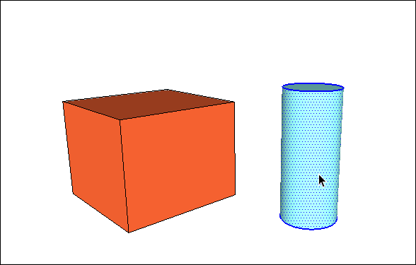
Move and rotate your cutting shape so that it intersects with the shape you’d like to cut. (See Moving Entities Around and Flipping and Rotating for help.) Leave your cutting shape selected, as shown in the figure.移动并旋转切割形状,使其与要切割的形状相交。(有关帮助,请参阅“移动周围的实体”和“翻转和旋转”。)保持切割形状处于选中状态,如图所示。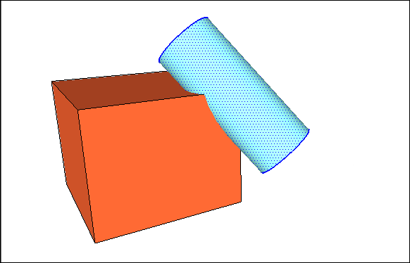
Context-click the cutting shape, and choose Intersect Faces > With Model from the menu that appears. The command tells SketchUp to create edges where the two shapes intersect.右键单击切割形状,然后从显示的菜单中选择“相交面>与模型相交”。命令告诉SketchUp在两个形状相交的位置创建边。With the Eraser tool (使用“橡皮擦”工具( ), erase or move the geometry that you don’t want to keep. ),擦除或移动不想保留的几何图形。
In the following figure, you see how the box shape is changed after the cylinder is erased.在下图中,您可以看到圆柱体被擦除后长方体形状是如何变化的。Tip:Remember you can hold down the scroll wheel on your mouse to temporarily switch to the Orbit tool, so you can orbit around and find all the geometry you want do delete. (See Erasing and Undoing for details about the Eraser tool.)请记住,您可以按住鼠标上的滚轮暂时切换到“动态观察”工具,这样您就可以动态观察并找到要删除的所有几何体。(有关橡皮擦工具的详细信息,请参阅擦除和撤消。)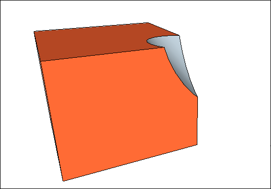
Intersect with Model creates edges in the current context. If your shapes are groups or components, you can create the intersecting lines either within the group or outside it. “与模型相交”在当前上下文中创建边。如果形状是组或组件,则可以在组内或组外创建相交线。When you create the intersecting lines outside a group’s context, you can easily separate your original shapes from the edges that SketchUp creates, as shown in the following figure. 在组上下文之外创建相交线时,可以轻松地将原始形状与SketchUp创建的边分开,如下图所示。See Organizing a Model for details about groups and Adding Premade Components and Dynamic Components for an introduction to groups and components, respectively.
Trimming one solid with another用一个实体修剪另一个实体
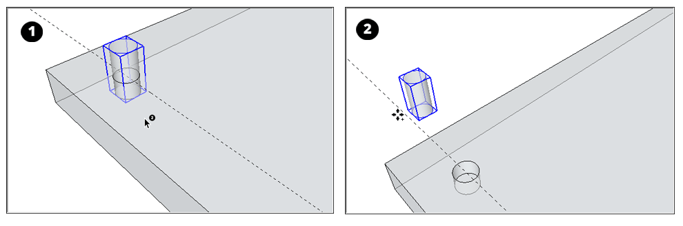
With the Trim tool, you cut one solid entity with another, just like a subtraction. However, when you use the Trim tool, the cutting solid remains in the model. So, if you use a peg to trim a board, the peg remains after it cuts the board. Like all the Solid tools, the Trim tool works only if two solid entities overlap.使用“修剪”工具,您可以将一个实体与另一个实体切割在一起,就像减法一样。但是,使用修剪工具时,切割实体仍保留在模型中。所以,如果你用钉子修剪一块木板,钉子在切割木板后仍然存在。与所有实体工具一样,修剪工具仅在两个实体重叠时才起作用。
To perform a trim, follow these steps:要执行修剪,请执行以下步骤:
Select the Trim tool (选择“修剪”工具( ).)。Tip:
Until you hover over a solid group or component, you see an arrow cursor with a circle and a slash.在将鼠标悬停在实体组或组件上之前,您会看到一个带有圆圈和斜线的箭头游标。When your cursor hovers over a solid group or component, the red circle and slash change to a black 1 inside a circle, and you see a Solid Group or Solid Component ScreenTip.当游标悬停在实体组或组件上时,红色圆圈和斜线会变为圆圈内的黑色1,您会看到实体组或实体组件屏幕提示。Click to select the cutting group or component.单击以选择切割组或组件。In the example shown here, select the peg first to make a hole in the board. After you make a selection, the 1 next to the cursor becomes a 2.在此处显示的示例中,首先选择钉子在板上打孔。选择后,游标旁边的1将变为2。Click the group or component that you want to cut. The cutting group remains, but makes a hole in the second selection. The result is hard to see at first (refer to Callout 1). However, move the peg out of the hole, as shown in Callout 2, and you see the hole in the board.单击要剪切的组或组件。切割组仍然存在,但在第二个选择中打了一个洞。起初很难看到结果(请参阅标注1)。但是,将栓钉移出孔中,如详图2所示,您将看到板上的孔。
Leaving only the intersecting geometry只留下相交的几何图形
With SketchUp Pro’s Intersect tool (使用SketchUp Pro的“相交”工具(![]() ), you select two or more overlapping solid entities, and only the intersecting geometry is left behind.
), you select two or more overlapping solid entities, and only the intersecting geometry is left behind.![]() ),可以选择两个或多个重叠的实体,只留下相交的几何图形。
),可以选择两个或多个重叠的实体,只留下相交的几何图形。
To perform an intersection, follow these steps:要执行交叉操作,请执行以下步骤:
Select the Intersect tool (选择“相交”工具( ).)。Tip:
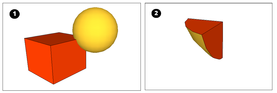
Until you hover over a solid group or component, you see an arrow cursor with a circle and a slash.在将鼠标悬停在实体组或组件上之前,您会看到一个带有圆圈和斜线的箭头游标。When your cursor hovers over a solid group or component, the red circle and slash change to a black 1 inside a circle, and you see a Solid Group or Solid Component ScreenTip.当游标悬停在实体组或组件上时,红色圆圈和斜线会变为圆圈内的黑色1,您会看到实体组或实体组件屏幕提示。Select a solid entity that you want to use in the intersection.选择要在交点中使用的实体。Select one or more additional solids that overlap your initial selection. The resulting intersecting geometry remains. In this example, the intersection of the box and the sphere (Callout 1) creates a point with a rounded base (Callout 2).选择一个或多个与初始选择重叠的其他实体。生成的相交几何图形将保留。在此示例中,长方体和球体的交点(标注1)创建了一个具有圆角底的点(标注2)。
Splitting solids分裂固体
With the Split tool (使用“分割”工具(),可以沿相交边分割重叠的实体。要执行拆分,请执行以下步骤:![]() ), you can divide overlapping solid entities along their intersecting edges. To perform a split, follow these steps:
), you can divide overlapping solid entities along their intersecting edges. To perform a split, follow these steps:
Select the Split tool (
 ).Tip:
Until you hover over a solid group or component, you see an arrow cursor with a circle and a slash. When your cursor hovers over a solid group or component, the red circle and slash change to a black 1 inside a circle, and you see a Solid Group or Solid Component ScreenTip.在将鼠标悬停在实体组或组件上之前,您会看到一个带有圆圈和斜线的箭头游标。当游标悬停在实体组或组件上时,红色圆圈和斜线会变为圆圈内的黑色1,您会看到实体组或实体组件屏幕提示。Click a solid entity.单击实体。Click another solid entity that intersects your first selection. SketchUp splits all the geometry along the edges where the selected solids intersect. For example, in the figure, the two groups shown on the left split into 3 groups, as shown on the right.单击与第一个选择相交的另一个实体。SketchUp沿着选定实体相交的边分割所有几何图形。例如,在图中,左侧显示的两组分为3组,如右侧所示。
Fixing models with Solid Inspector in SketchUp Web在SketchUp Web中使用Solid Inspector修复模型
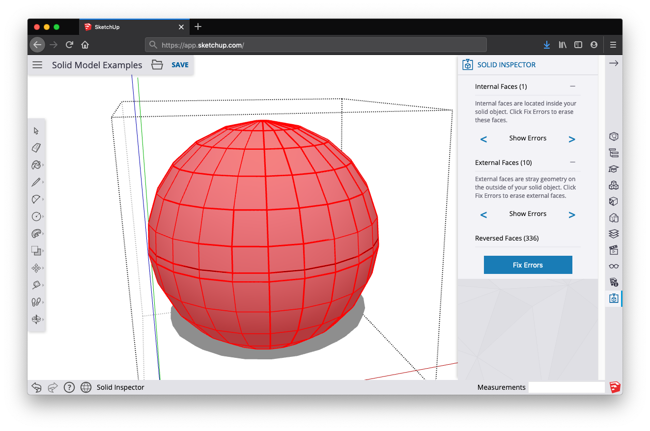
As geometry gets more and more complex, small errors may prevent models from being manifold. 随着几何变得越来越复杂,小误差可能会阻止模型的流形。Solid Inspector in SketchUp for Web is a utility that helps you prepare models for 3D printing by finding and fixing problems that prevent SketchUp from classifying your model as a solid. This inspection is also useful for fixing 3D models for Solid Tool operations.SketchUp for Web中的Solid Inspector是一个实用程序,通过查找和修复阻止SketchUp将模型分类为实体的问题,帮助您为3D打印准备模型。此检查对于固定Solid Tool操作的3D模型也很有用。
Activate Solid Inspector激活实体检查器
Find the Solid Inspector utility at the bottom of the right-hand panel menu in SketchUp for Web. When you activate the utility, you’ll be prompted to select a group or component. With a selected object, click Run Inspector to proceed. When an error is identified, click on its name to learn more about it; use arrow icons to fly the SketchUp camera to the individual problems in your model.在SketchUp for Web的右侧面板菜单底部找到Solid Inspector实用程序。激活该实用程序时,系统将提示您选择一个组或组件。对于选定的对象,单击“运行检查器”继续。当识别出错误时,单击其名称以了解更多信息;使用箭头图标将SketchUp相机飞到模型中的各个问题。
Automatically Fixable Errors可自动修复的错误
Several errors that Solid Inspector detects can be fixed automatically. Solid Inspector errors are identified by red-highlighted geometry, so that you can take a closer look before giving Solid Inspector the ‘okay’ to automatically fix errors. Automatically fixable errors include:Solid Inspector检测到的几个错误可以自动修复。Solid Inspector错误由红色突出显示的几何体标识,因此您可以在给予Solid Insector“确定”自动修复错误之前仔细查看。可自动修复的错误包括:
Reversed faces: Solid Inspector is also a handy utility for making sure that face normals are facing outwards.反转面:Solid Inspector也是一个方便的实用程序,用于确保面法线朝外。Stray edges: Surplus edge geometry that does not define any face.杂散边:未定义任何面的多余边几何体。Internal and external faces: Stray geometry on the inside or outside of your model.内外面:模型内部或外部的杂散几何体。Face Holes: A hole in an exterior face. Easy fix for Solid Inspector.面孔:外表面上的孔。Solid Inspector易于修复。
Manually Fixable Errors手动修复错误
Some errors cannot be automatically fixed by Solid Inspector, and must be manually repaired using SketchUp’s drawing (or Eraser) tools. After fixing a few manual errors, it’s a good idea to re-run the Inspector to see if your changes have cleaned up the model enough for automatic fixing to take over. Manually fixable errors include:Solid Inspector无法自动修复某些错误,必须使用SketchUp的绘图(或橡皮擦)工具手动修复。在修复了一些手动错误后,最好重新运行检查器,看看您的更改是否已经清理了足够的模型,以便自动修复接管。可手动修复的错误包括:
Border holes: These holes share at least one edge with the surface of a solid. These errors can be manually fixed by drawing over or erasing the highlighted geometry. As you go, try re-running the inspector to see if you’ve done enough repair go for Solid Inspector to automatically fix the rest of the model.边界孔:这些孔与实体的表面至少共享一条边。这些错误可以通过绘制或擦除突出显示的几何图形来手动修复。在执行过程中,尝试重新运行检查器,查看是否已完成足够的修复,以便Solid inspector自动修复模型的其余部分。Nested groups/components: Nested objects in groups or components can lead to confusing STL exports for 3D printers. Solid Inspector won’t fix these automatically, but you can use the Inspector to look at each nested instance and decide whether to delete it or explode the geometry into your model.嵌套组/组件:组或组件中的嵌套对象可能会导致3D打印机的STL导出混淆。Solid Inspector不会自动修复这些问题,但您可以使用Inspector查看每个嵌套实例,并决定是删除它还是将几何体分解到模型中。Image entities: Images imported into SketchUp can’t be exported to an STL file and also inhibit Solid Tool operations. Solid Inspector will prompt you about these errors, but you’ll need to delete them manually. Consider making Image entities into components. They are easy to temporarily delete from your model in this respect. Also, painting a face with an image texture doesn’t impact Solid-ness.图像实体:导入SketchUp的图像不能导出到STL文件,也不能禁止Solid Tool操作。Solid Inspector将提示您这些错误,但您需要手动删除它们。考虑将图像实体转化为组件。在这方面,它们很容易从您的模型中临时删除。此外,用图像纹理绘制面部不会影响“实体”。Short edges: Very small geometry can cause problems in 3D prints or solid operations. Since these problems are unpredictable -- and short edges do not disqualify objects as solid in SketchUp -- Solid Inspector will not fix these errors automatically. However, Solid Inspector is a great way to find and evaluate these problem areas.短边:非常小的几何形状可能会在3D打印或实体操作中造成问题。由于这些问题是不可预测的,并且短边不会取消对象在SketchUp中作为实体的资格,因此solid Inspector不会自动修复这些错误。然而,Solid Inspector是发现和评估这些问题领域的好方法。
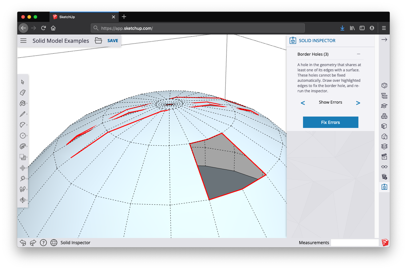
Show Errors显示错误
When you have multiple errors that cannot be fixed automatically, it’s useful to use the “Show Errors” command to navigate between individual problems that you’ll need to manually fix. Use the left and right arrows to cycle through all the errors of a certain type that Solid Inspector has identified; the SketchUp camera will zoom to the problem area.当您有多个无法自动修复的错误时,使用“显示错误”命令在需要手动修复的各个问题之间导航是有用的。使用左右箭头循环浏览Solid Inspector识别出的特定类型的所有错误;SketchUp相机将缩放到问题区域。