Adjusting the Drawing Axes调整绘图轴
The red, blue, and green axes seen when you first open a new SketchUp model are not only starting points but guides you can use throughout the modeling process. Adjusting the SketchUp drawing axes makes drawing a 3D model easier. Here's some examples:首次打开新SketchUp模型时看到的红色、蓝色和绿色轴不仅是起点,也是您在整个建模过程中可以使用的指导。调整SketchUp绘图轴可以更轻松地绘制3D模型。以下是一些示例:
Using tools that modify geometry based on the drawing axes:使用基于图形轴修改几何图形的工具:When you align the edges that you want to modify with the axes, it's easier to modify your geometry.当您将要修改的边与轴对齐时,修改几何图形会更容易。Creating a 3D model by tracing a floor plan:通过跟踪平面图创建三维模型:Aligning the edges of a rectangular floor plan with the red and green axes helps you trace your floor plan.将矩形平面图的边缘与红色和绿色轴对齐可以帮助您跟踪平面图。The SketchUp inference engine highlights edges parallel to an axis as you draw them with the Line tool.当您使用线工具绘制平行于轴的边时,SketchUp推理引擎会亮显这些边。
Geolocating a model on terrain:在地形上对模型进行地理定位:If you're drawing a geolocated model, you probably want to align the drawing axes to the cardinal directions those axes represent, helping situate your model on the terrain correctly.如果您正在绘制一个地理定位模型,您可能希望将绘图轴与这些轴所代表的基本方向对齐,以帮助将模型正确地放置在地形上。(If you're not familiar with these modeling techniques, learn more about modeling terrain and working with TINs.)(如果您不熟悉这些建模技术,请了解有关地形建模和TIN使用的更多信息。)Casting realistic shadows:投射逼真的阴影:Geolocated models let you see how your model looks at different times of day. Aligning your axes to the cardinal directions helps you convey a sense of realism in your model.地理定位模型可以让你看到你的模型在一天中不同时间的样子。将轴与基本方向对齐有助于在模型中传达真实感。
In SketchUp you can adjust the drawing axes in a way that best suits your model, or even hide them!在SketchUp中,您可以以最适合模型的方式调整绘图轴,甚至可以隐藏它们!
Moving and Rotating移动和旋转
To adjust the axes with your mouse, follow these steps:要使用鼠标调整轴,请执行以下步骤:
Activate the Axes tool (从以下位置之一激活轴工具( ) from one of the following locations:):
The Construction toolbar“构造”工具栏The Large Tool Set (Windows)大型工具集(Windows)The Tool palette (macOS)工具选项板(macOS)Axes under the Tools menu工具菜单下的轴The Place option seen in the context menu when right-clicking the axes.右键单击轴时,在上下文菜单中看到的“放置”选项。
If you want to instantly place your axes, simply double click at the desired location. You can also double click at any point outlined in the steps below to place the axes as seen in the modeling window.如果要立即放置轴,只需在所需位置双击即可。您还可以在下面步骤中概述的任何点双击,以放置建模窗口中看到的轴。Tip: As you reorient the drawing axes, keep an eye on the blue axis. Unless you want to flip your model (and the flip and rotate features offer better ways to do that), make sure the blue axis points up.:重新定位绘图轴时,请注意蓝色轴。除非你想翻转模型(翻转和旋转功能提供了更好的方法),否则请确保蓝色轴指向上方。It is possible for it to point down or to the side as you hover the mouse cursor around looking for new axis points.当您将鼠标游标悬停在周围寻找新的轴点时,它可以指向下方或侧面。For more precise placement, click once to place the axes origin point. A dotted red axis will extend to your mouse cursor.要更精确地放置,请单击一次以放置轴原点。红色虚线轴将延伸到鼠标游标。Tip: After you place the origin or select your first direction, tap Alt (Microsoft Windows) or Command (macOS) to alternate the axis orientation leading to your mouse cursor.:放置原点或选择第一个方向后,点击Alt(Microsoft Windows)或Command(macOS)以交替指向鼠标游标的轴方向。Click to place the second axis. Another dotted axis, representing the third axis, extends from your mouse cursor.单击以放置第二个轴。另一个虚线轴代表第三个轴,从鼠标游标延伸。Click to place the third axis.单击以放置第三个轴。Tip: Set your axes origin point at the bottom corner of an object in your model. You can then set your other axes aligned with edges and receive on-screen inference cues.:将轴原点设置在模型中对象的下角。然后,您可以将其他轴设置为与边对齐,并接收屏幕上的推理提示。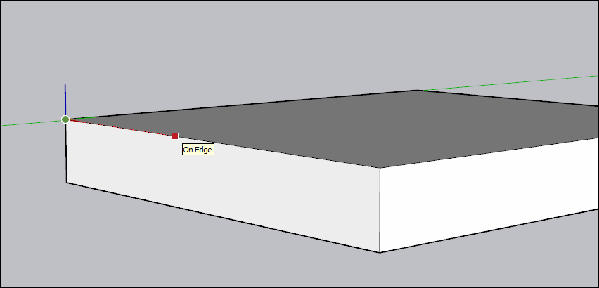
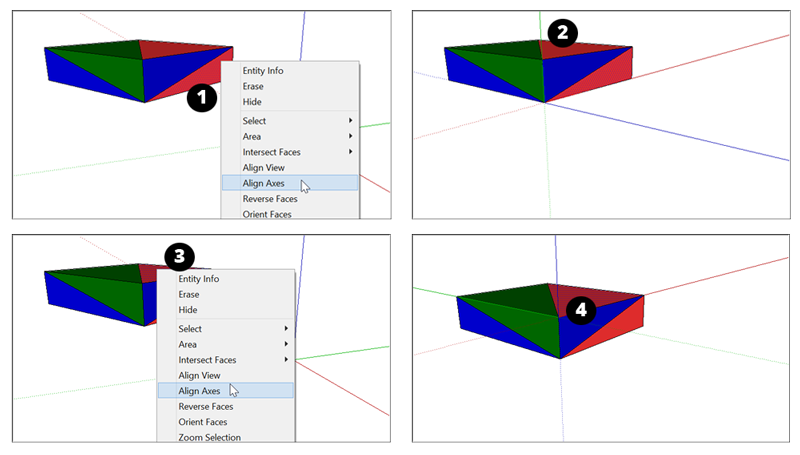
To align the axes to a face, context-click the face and select Align Axes. How the axes align depends on what planes that face exists in. Here's an example of how it works:要将轴与面对齐,请右键单击该面并选择“对齐轴”。轴的对齐方式取决于其所在的平面。以下是一个工作原理示例:
If you select a face in the blue-red or blue-green plane you rotate the axes 90 degrees (#1). Notice how the green axis points up and the blue axis turns on its side (#2).如果在蓝-红或蓝-绿平面中选择一个面,则将轴旋转90度(#1)。请注意绿色轴是如何向上指向的,蓝色轴是如何侧向转动的(#2)。If you select a face in the red-green plane (#3), the axes don't rotate, but the ground plane becomes aligned to the selected plane (#4).如果在红绿色平面(#3)中选择一个面,则轴不会旋转,但地平面将与选定平面对齐(#4)。
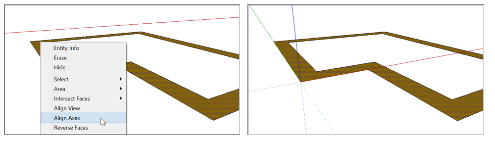
This is most useful when you're drawing a 3D model from a 2D shape drawn on the ground plane. Select the 2D face on the ground plane, and the drawing axes become aligned to the lower-left corner before you start drawing in 3D.当您从地平面上绘制的二维形状绘制三维模型时,这是最有用的。在地平面上选择二维面,在开始三维绘图之前,绘图轴将与左下角对齐。
If you want even more precision, you can use Move Axes.如果您希望获得更高的精度,可以使用“移动轴”。
MacOS
Context-click an empty area on an axis and select Move.右键单击轴上的空白区域,然后选择“移动”。In the Move Axes modal, enter how far you want to move and rotate each axis in the units of measurement you've specified for your model.在“移动轴”模式中,输入您希望以为模型指定的测量单位移动和旋转每个轴的距离。Click OK.单击“确定”。
Windows
Context-click an empty area on an axis and select Move.右键单击轴上的空白区域,然后选择“移动”。In the Move Sketching Context modal, enter how far you want to move and rotate each axis in the units of measurement you've specified for your model.在“移动草图上下文”模式中,输入您希望以为模型指定的测量单位移动和旋转每个轴的距离。Click OK.单击“确定”。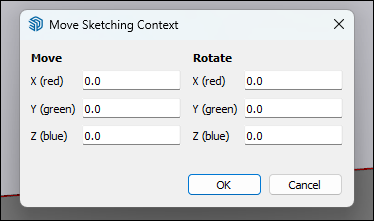
Resetting the drawing axes重置图形轴
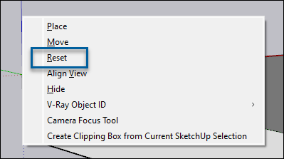
After moving your axes from here to there to everywhere else, you can move the axes back to their default position easily. Simply context-click an axis and choose Reset.将轴从这里移动到那里再移动到其他任何地方后,您可以轻松地将轴移回默认位置。只需右键单击轴并选择“重置”。
Hiding the drawing axes隐藏图形轴
Don't want to see those pesky axes in your model? Hide them using one of the following methods:不想在你的模型中看到那些讨厌的斧头吗?使用以下方法之一隐藏它们:
Context-click an open area on an axis and select Hide.右键单击轴上的空白区域,然后选择“隐藏”。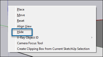
Select Axes from the View menu, removing the check next to it. Select Axes again to un-hide the axes.从“视图”菜单中选择“轴”,删除其旁边的复选框。再次选择“轴》以取消隐藏轴。
Aligning the drawing axes with the cardinal directions将图形轴与基本方向对齐
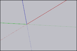
Each axis has a solid line on one side of the origin and a dotted line on the other side of the origin. The solid blue line leads up from the origin and the dotted blue line leads down. The remaining lines correspond to one of the cardinal directions (north, south, east, west).每个轴在原点的一侧都有一条实线,在原点的另一侧都有虚线。蓝色实线从原点向上延伸,蓝色虚线向下延伸。其余的线条对应于一个主要方向(北、南、东、西)。
| North | |
| South | |
| East | |
| West |